


Page 67 - ASF Katalog 2018 en
P. 67
9                                                       WALINGS


         Waling design

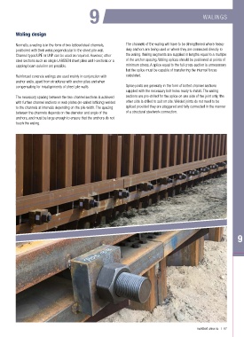
         Normally, a waling is in the form of two latticed steel channels,   The channels of the waling will have to be strengthened where heavy-
         positioned with their webs perpendicular to the sheet pile wall.   duty anchors are being used or where they are connected directly to
         Channel types UPE or UNP can be used as required. However, other   the waling. Waling segments are supplied in lengths equal to a multiple
         steel sections such as single LARSSEN sheet piles and I-sections or a   of the anchor spacing. Waling splices should be positioned at points of
         capping beam solution are possible.                    minimum stress. A splice equal to the full cross-section is unnecessary
                                                                but the splice must be capable of transferring the internal forces
         Reinforced concrete walings are used mainly in conjunction with   calculated.
         anchor walls, apart from structures with anchor piles and when
         compensating for misalignments of sheet pile walls.    Splice joints are generally in the form of bolted channel sections
                                                                supplied with the necessary bolt holes ready to install. The waling
         The necessary spacing between the two channel sections is achieved   sections are pre-drilled for the splice on one side of the joint only; the
         with further channel sections or web plates (so-called latticing) welded   other side is drilled to suit on site. Welded joints do not need to be
         to the channels at intervals depending on the pile width. The spacing   spliced provided they are staggered and fully connected in the manner
         between the channels depends on the diameter and angle of the   of a structural steelwork connection.
         anchors, and must be large enough to ensure that the anchors do not
         touch the waling.


                                                                                                   mail@asf-anker.de   |   67

