
Page 9 - ASF Katalog 2018 en
P. 9
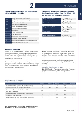
2                                                 ANCHORAGES


         The verification format for the ultimate limit         The design resistances are calculated using
         state to DIN EN 1993-5 is:                             the following equations from EAU 2004, R 20,
                                                                for the shaft and core cross-sections:


          F      = Design tensile resistance of anchor thread    Design resistance, thread:    F   = min (F  ; F  )
          tt,Rd                                                                               t,Rd    tt,Rd  yt,Rd
          F      = Design tensile resistance of anchor shaft     Failure in thread:            F  = k*F *A /γ
          tg,Rd                                                                               tt,Rd  t  ua  s  M2
                 = Design resistance at yield stress /           Yield stress, thread:         F   = F *A /γ
          F                                                                                   yt,Rd  y  s  M0
          yt,Rd    0.2% proof stress of anchor thread
                 = Design resistance at yield stress /           Design resistance, shaft:     F   = min (F  ; F  )
          F                                                                                   g,Rd    tg,Rd   yg,Rd
          yg,Rd    0.2% proof stress of anchor shaft             Failure in shaft:             F   = A *F /γ
          K      = Notch factor                                                               tg,Rd  g  ua  M2
           t                                                     Yield stress, shaft:          F yg,Rd  = F *A /γ M0
                                                                                                     g
                                                                                                   y
          F      = Tensile strength of anchor
          ua
          F      = Yield stress of anchor
          y                                                      Design resistance, anchor:    F   = min (F  ; F )
          A      = Stressed cross-sectional area, thread                                      u,Rd    t,Rd  g,Rd
           s
          A      = Gross cross-sectional area, shaft
           g
          γ      = Partial safety factor for anchor shaft stressed up to failure
           M2
          γ      = Partial safety factor for anchor shaft
           M0
         Corrosion protection
         The simplest and least expensive way of achieving effective corrosion   However, should you require coated anchor materials, then any form
         protection is to increase the diameter of the bar and the associated   of coating is possible. All customary coating systems involving the
         thread. The table below will help you decide whether increasing the   application of paint on surfaces prepared by abrasive blasting can be
         size of the steel is worthwhile for your structure or whether a coating   applied.
         system would be more appropriate.
                                                                Besides coating, the methods most frequently used are wrapping
         Please note that every coating increases the price per kilogram,   with Densoplast tape or hot-dip galvanising to EN ISO 1461 (except
         prolongs the fabrication time for the anchor, is almost always damaged   ASF600).
         during transport and installation and from the environmental viewpoint
         is in some cases at least questionable.                Corrosion chart for steel anchors
                                                                EN 1993-5, Table 4-1 – Recommended values for loss of thickness
                                                                [mm] due to corrosion in soils, with or without groundwater


         Required design working life

                                                             5 Years    25 Years   50 Years    75 Years   100 Years
          Non-compacted and non-aggressive fills (clay, slate, sand, silt)  0.18  0.7  1.2      1.7         2.2
          Freshwater (river, canal, ...) in the region of the waterline  0.18  0.55  0.9        1.15        1.4
          Severely polluted freshwater (wastewater, industrial wastewater)
          in the region of the waterline                      0.3         1.3        2.3        3.3         4.3
          Seawater in a temperate climate in the region of the waterline  0.55  1.9  3.75       5.6         7.5
          (low water and splash water zones)
          Seawater in a temperate climate in the underwater or tidal zones  0.25  0.9  1.75     2.6         3.5


         Note: For compacted fills, EN 1993-5 permits the corrosion rates to be halved.
         EN 1993-5, Table 4-2 – Recommended values for loss of thickness [mm]
                                                                                                    mail@asf-anker.de   |   9